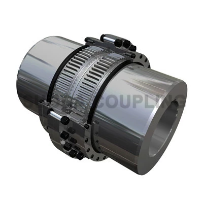
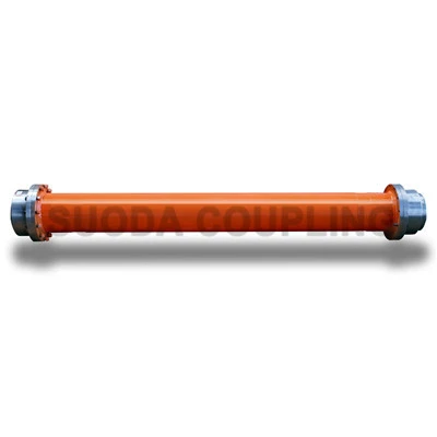
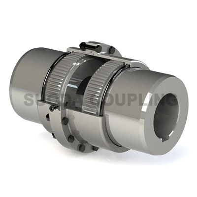
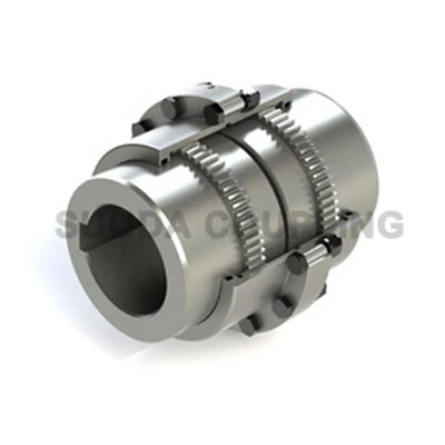
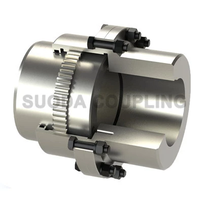
Hub Style Gear Coupling - GZB Type
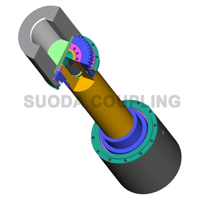
Key Specifications / Features
Model No.: Suoda 15 GZ 07 Hits: 1922
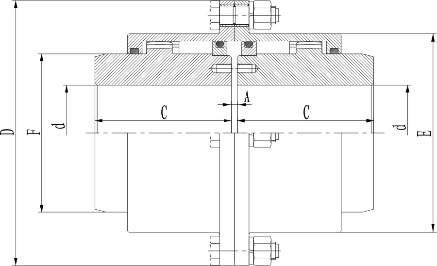
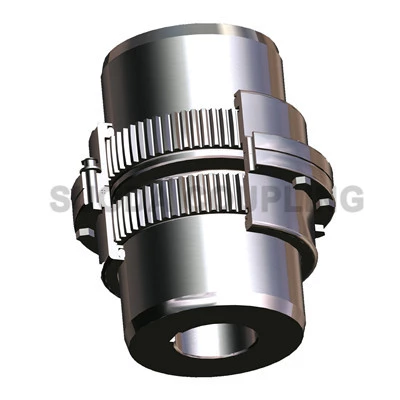
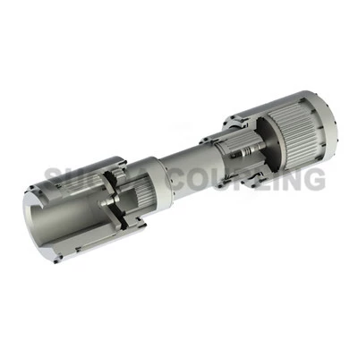
China Hub Style Gear Coupling Manufacturer Suoda Offers Hub Gear Couplings, GZB Type Gear Couplings, can be Widely in Many Fields for Power Transmission.
Request a quote
Share
Tags:
Detail Infomation
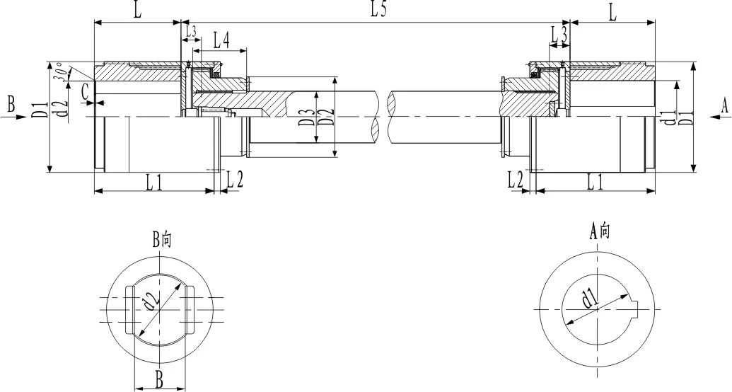
| SIZE |
NOMINAL TORQUE kN·m |
CYLINDRICAL SHAFT HOLE SIZE |
FLAT-SHAPED SHAFT HOLE SIZE |
D1 | D2 | D3 | L1 | L2 | |||
| d1,d2 | Lmax | d2max | Lmax | Bmax | |||||||
| J1 Type | |||||||||||
| GZB7 | 63 | 140-190 | 202-282 | 190 | 282 | 140 | 280 | 200 | 160 | 336-416 | 38 |
| GZB8 | 80 | 160-200 | 242-282 | 200 | 282 | 160 | 300 | 220 | 180 | 392-432 | 44 |
| GZB9 | 100 | 170-220 | 242-282 | 220 | 282 | 170 | 330 | 230 | 200 | 392-432 | 44 |
| GZB10 | 125 | 190-240 | 282-330 | 240 | 330 | 180 | 355 | 250 | 220 | 442-490 | 51 |
| GZB11 | 200 | 190-260 | 282-330 | 260 | 330 | 200 | 410 | 290 | 240 | 457-505 | 51 |
| GZB12 | 315 | 240-300 | 330-380 | 300 | 380 | 220 | 460 | 320 | 260 | 518-568 | 57 |
| GZB13 | 450 | 280-340 | 380-450 | 340 | 450 | 250 | 510 | 360 | 300 | 596-666 | 57 |
| GZB14 | 560 | 300-360 | 380-450 | 360 | 450 | 280 | 560 | 400 | 320 | 628-698 | 64 |
| GZB15 | 710 | 340-400 | 450-540 | 400 | 540 | 300 | 610 | 430 | 350 | 716-806 | 64 |
| GZB16 | 900 | 360-420 | 550-650 | 420 | 650 | 320 | 660 | 460 | 380 | 842-942 | 64 |
| GZB17 | 1120 | 400-460 | 650 | 460 | 650 | 350 | 710 | 500 | 420 | 964 | 64 |
| GZB18 | 1250 | 420-500 | 650 | 500 | 650 | 380 | 760 | 540 | 460 | 990 | 76 |
| GZB19 | 1600 | 440-530 | 650-800 | 530 | 800 | 400 | 810 | 580 | 500 | 1005-1155 | 76 |
| GZB20 | 2000 | 450-560 | 650-800 | 560 | 800 | 420 | 860 | 600 | 530 | 1031-1181 | 76 |
| GZB21 | 2240 | 480-600 | 650-800 | 600 | 800 | 450 | 910 | 650 | 560 | 1056-1206 | 76 |
| GZB22 | 2800 | 530-630 | 800 | 630 | 800 | 480 | 965 | 680 | 600 | 1230 | 82 |
| GZB23 | 3150 | 560-670 | 800-900 | 670 | 900 | 500 | 1000 | 710 | 630 | 1250-1350 | 82 |
| Size | L3 | L4 | L5min | L6 | Cmax |
QUALITY Wt(kg) |
ROTATIONAL INERTIA kg.m2 |
GREASE COMSUPTION Ml |
||
|
L5min QUALITY Wt |
The quality of growth per meter 1m/Wt |
L5min of rotational inertia |
The rotational inertia of the growth per meter |
|||||||
| GZB7 | 85 | 200 | 800 | 5 | 19 | 380 | 158 | 4.26 | 0.501 | 1400 |
| GZB8 | 95 | 220 | 1000 | 5 | 20 | 480 | 200 | 6.02 | 0.81 | 1800 |
| GZB9 | 95 | 230 | 1000 | 5 | 22 | 550 | 247 | 7.95 | 1.24 | 2100 |
| GZB10 | 98 | 250 | 1000 | 5 | 24 | 720 | 298 | 12.7 | 1.8 | 2500 |
| GZB11 | 106 | 280 | 1200 | 5 | 26 | 1110 | 355 | 25.95 | 2.56 | 3000 |
| GZB12 | 112 | 300 | 1200 | 6 | 30 | 1480 | 417 | 43.43 | 3.52 | 4000 |
| GZB13 | 136 | 340 | 1400 | 6 | 34 | 2020 | 555 | 71.76 | 6.24 | 5200 |
| GZB14 | 145 | 380 | 1500 | 6 | 36 | 2600 | 631 | 114.4 | 8.1 | 6500 |
| GZB15 | 160 | 400 | 1500 | 6 | 40 | 3300 | 755 | 178 | 11.6 | 8000 |
| GZB16 | 172 | 440 | 1600 | 10 | 42 | 4300 | 890 | 272 | 16 | 10000 |
| GZB17 | 182 | 480 | 1800 | 10 | 46 | 5500 | 1090 | 392 | 24 | 12000 |
| GZB18 | 195 | 520 | 2000 | 10 | 50 | 6700 | 1310 | 553 | 35 | 15000 |
| GZB19 | 215 | 540 | 2000 | 10 | 53 | 8350 | 1540 | 805 | 48 | 16500 |
| GZB20 | 225 | 560 | 2000 | 10 | 56 | 9500 | 1730 | 1024 | 61 | 18500 |
| GZB21 | 236 | 600 | 2500 | 10 | 60 | 11500 | 1930 | 1334 | 75.66 | 21000 |
| GZB22 | 246 | 640 | 2500 | 13 | 63 | 12600 | 2220 | 1621 | 99.9 | 24000 |
| GZB23 | 265 | 680 | 2500 | 13 | 67 | 17900 | 2450 | 2579 | 122 | 27000 |
Notes:
1. Quality and rotational inertia are approximate values calculated according to the maximum diameter of cylindrical shaft holes and the intermediate shaft length of L5min.
2. Types of coupling shaft holes: generally using cylinder-shaped drive end and flat-shaped driven end. If necessary, both ends can be cylinder-shaped.
3. Cmax is calculated by one-tenth diameter of flat-shaped shaft hole, namely C=0.1d2 (this result must be rounding.)
4. When shaft holes are flat-shaped, tolerance limit of d2 and B is H9.

