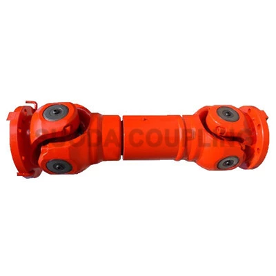
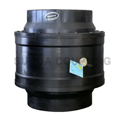
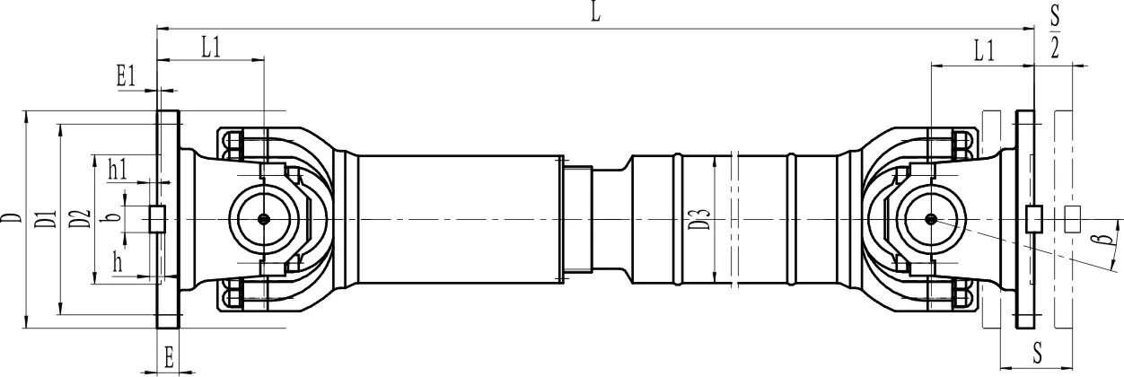
Non Telescopic Flanged U-Joint - UCX Type
Key Specifications / Features
Model No.: Suoda 15 UCX 01 Hits: 2725
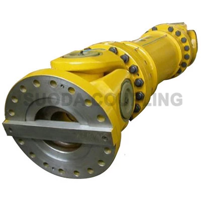
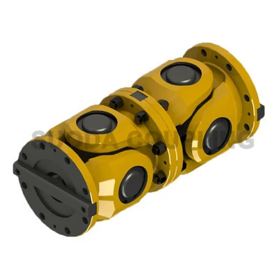
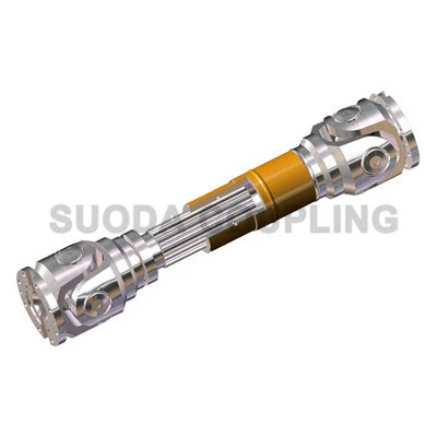
China Non Telescopic Flanged Universal Joint Supplier Suoda Offers Non Telescopic U-Joints, Flange Type U-Joints, UCX Type U-Joints, Big Transmission Torque.
Request a quote
Share
Tags:
Detail Infomation

| Type |
Rotational Diameter mm |
Norminal Torque Tn kN.m |
Fatigue Torque Tf kN.m |
Axial Swing Angle β° |
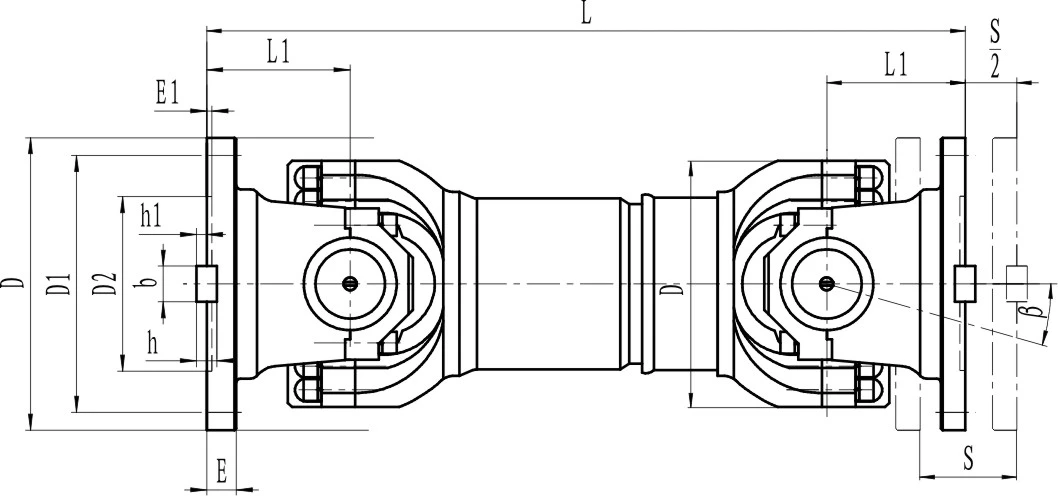
Dimension,mm |
Inertial Moment I kg.m² |
Weight G kg |
|||||||||||
| Lmin |
D1 (js11) |
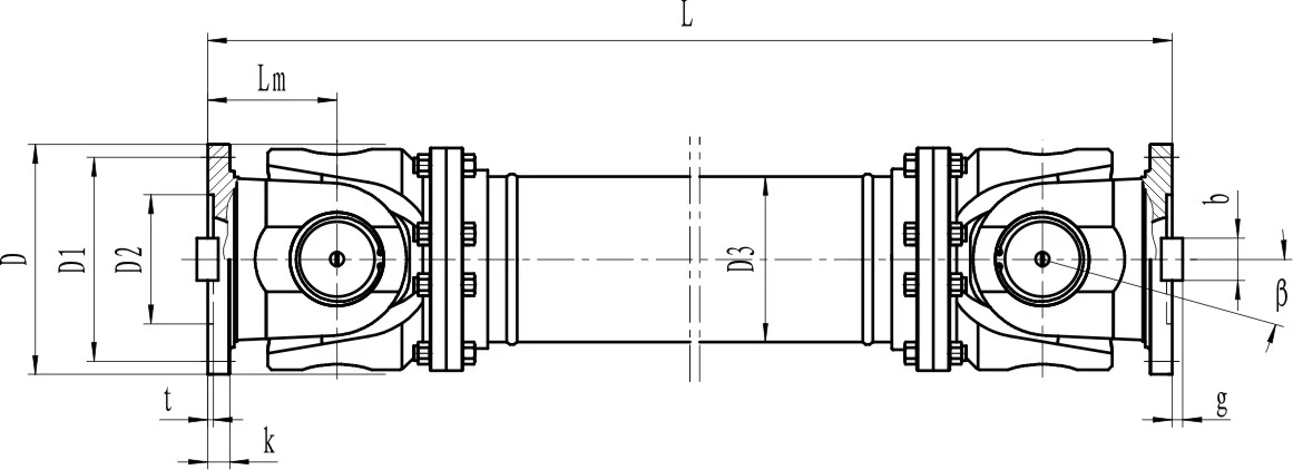
D2 (H7) | D3 | Lm | n-d | k | t | B (h9) | g | Lmin |
Increase per 100mm |
Lmin |
Increase per 100mm |
|||||
| UCX 180 | 180 | 12.5 | 6.3 | ≤25 | 560 | 155 | 105 | 114 | 110 | 8-17 | 17 | 5.0 | - | - | 0.248 | 0.0070 | 58 | 2.8 |
| UCX 225 | 225 | 40 | 20 | ≤15 | 610 | 196 | 135 | 152 | 120 | 8-17 | 20 | 5.0 | 32 | 9.0 | 0.636 | 0.0234 | 93 | 4.9 |
| UCX 250 | 250 | 63 | 31.5 | ≤15 | 715 | 218 | 150 | 168 | 140 | 8-19 | 25 | 6.0 | 40 | 12.5 | 1.352 | 0.0277 | 143 | 5.3 |
| UCX 285 | 285 | 90 | 45 | ≤15 | 810 | 245 | 170 | 194 | 160 | 8-21 | 27 | 7.0 | 40 | 15.0 | 2.664 | 0.0510 | 220 | 6.3 |
| UCX 315 | 315 | 125 | 63 | ≤15 | 915 | 280 | 185 | 219 | 180 | 10-23 | 32 | 8.0 | 40 | 15.0 | 4.469 | 0.0795 | 300 | 8.0 |
| UCX 350 | 350 | 180 | 90 | ≤15 | 980 | 310 | 210 | 267 | 194 | 10-23 | 35 | 8.0 | 50 | 16.0 | 7.388 | 0.2219 | 412 | 15.0 |
| UCX 390 | 390 | 250 | 125 | ≤15 | 1100 | 345 | 235 | 267 | 215 | 10-25 | 40 | 8.0 | 70 | 18.0 | 13.184 | 0.2219 | 588 | 15.0 |
| UCX 440 | 440 | 355 | 180 | ≤15 | 1290 | 390 | 255 | 325 | 260 | 16-28 | 42 | 10.0 | 80 | 20.0 | 23.250 | 0.4744 | 880 | 21.7 |
| UCX 490 | 490 | 500 | 250 | ≤15 | 1360 | 435 | 275 | 325 | 270 | 16-31 | 47 | 12.0 | 90 | 22.5 | 40.750 | 0.4744 | 1173 | 21.7 |
| UCX 550 | 550 | 710 | 355 | ≤15 | 1510 | 492 | 320 | 426 | 305 | 16-31 | 50 | 12.0 | 100 | 22.5 | 68.480 | 1.3570 | 1663 | 34 |
| UCX 620 | 620 | 1000 | 500 | ≤15 | 1690 | 555 | 380 | 426 | 340 | 10-38 | 55 | 12.0 | 100 | 25.0 | 127.530 | 1.3570 | 2332 | 34 |
Notes:
1. Tf: Permitted torques according to fatigue strength under the alternating load.
1. Tf: Permitted torques according to fatigue strength under the alternating load.
2. L: Installation length, as required.

